
Modeling and mechanism of propagation of underground coal smoldering fires with thermal buoyancy driven
-
摘要:
地下煤火蔓延模型与机制研究对我国煤炭资源绿色安全开采具有重要意义。目前地下煤火阴燃正向蔓延模型主要存在问题:简化的煤燃烧单步反应忽略了水分蒸发和热解吸热反应对蔓延的重要影响作用;缺乏实验数据验证模型的有效性。为此,构建了包含水分蒸发、煤热解和碳氧化三步反应体系的地下煤火阴燃正向蔓延数学模型;采用COMSOL Multiphysics有限元软件数值计算了该理论模型;开展了不同地裂缝渗透性条件下热浮力驱动地下煤火阴燃正向蔓延实验,进行对比实验和数值计算。结果表明:构建的模型揭示了地下煤火阴燃蔓延供氧控制机制,不仅能预测地下煤火阴燃正向蔓延高温区域的温度和蔓延速率,而且还能合理地预测阴燃多步反应速率以及氧气、煤、碳和灰分质量分数的时空演化。
Abstract:Modeling and understanding of underground coal fire is of significance for green-and-safe mining of coal resources in China. Two issues remain unsolved in forward-propagation models of underground coal smoldering fires: one-step coal oxidation has been too simple so that endothermic reactions such as water evaporation and pyrolysis that have important influence on smoldering propagation of underground coal fires have been not considered; and models have not been validated via experimental data. In this work, a three-step chemical reaction scheme including water evaporation, coal pyrolysis, and char oxidation was employed and mathematic model in terms of forward propagation of underground coal smoldering fires was established. The theoretical model was numerically calculated using COMSOL Multiphysics finite element software. The theoretical model was numerically calculated using COMSOL Multiphysics finite element software, and the forward smoldering spread experiment of underground coal fire driven by thermal buoyancy under different ground crack permeability conditions was carried out. Comparison experiment and numerical calculation were carried out. Results show that the proposed model not only owns good capability to predict the peak temperature and velocity of smoldering propagation of underground coal fire, but also can inversely plot multiple step chemical reactions as well as spatiotemporal evolutions of oxygen and solid species mass fractions. In addition, the controlling mechanism of smoldering propagation of underground coal fires was further revealed.
-
地下煤火是全球性的重大灾害[1]。我国是受地下煤火灾害最为严重的国家之一[2-6]。地下煤火极难防治,其主要原因之一在于它在地下数十至近百米的地下深度、数十到上百年长时间的自维持性传播蔓延[2,3,7]。因此,理解蔓延机制和预测蔓延速率等有助于完善、改进地下煤火防控技术措施,对我国煤炭资源绿色安全开采和生态环境保护具有重要意义。
由于供氧受限,地下煤火主要以无焰、阴燃的方式蔓延。根据火蔓延与供氧的方向,可将阴燃蔓延分为正向蔓延和反向蔓延[8]:其中正向蔓延为火蔓延的方向与供氧方向一致;反之,则为反向蔓延。阴燃蔓延主要受供氧和热损失控制[9],地下岩层形成了比较好的保温环境;因此,地下煤火蔓延主要受供氧控制。地下煤火供氧驱动力主要包括风[10]、大气压波动[11]、自然风压[12]和热浮力(火风压)[13-15]。KREVOR等[16]针对美国科罗拉多San Juan Basin西北的某一处地下煤火,采用带有13C同位元素的CO2检测其供氧途径,研究表明地下煤火产生的热浮力是其自身燃烧所需供氧的重要驱动力;SONG等[17]通过地下煤火实验研究表明热浮力可能是地下煤火自维持持久蔓延的重要原因之一。
由于火区温度高且地质、气象条件复杂,地下煤火野外现场调研难度大、成本高。因此,构建可靠、稳定的数值计算模型是地下煤火蔓延经济且有效的研究手段,国内外学者对此开展了深入研究。HUANG等[18]建立了地下煤火二维稳态模型,预测了不同深度下的地下煤火温度分布;WOLF等[19]基于移动坐标构建了地下煤火二维准稳态模型,采用有限体积方法对该模型进行了数值计算,分析了地下煤火气体运移特点和火源深度影响。WESSLING等[20]建立了二维非稳态地下煤火蔓延模型,该模型不仅考虑了多孔介质传热传质,还包含了煤燃烧单步化学反应,且采用了operator-splitting方法对传质和化学反应进行分离操作,在数值计算方面实现了氧气运输对煤燃烧反应的控制,然后运用基于有限元方法的Rockflow进行数值模拟,分析了覆岩渗透率对地下煤火蔓延速率的影响;宋泽阳等[21]推导了地下煤火供氧受限条件下煤燃烧一步反应耗氧速率的估算式,在此基础上建立了二维非稳态地下煤火蔓延模型,运用有限元COMSOL Multiphysics分析了废弃巷道漏风和大气压波动对地下煤火的影响;WANG等[22]建立了多孔地下煤层的传热传质理论模型,采用有限差分-隐式解数值模拟分析了煤层倾角和孔隙率等地质条件对地下煤火蔓延速率的影响作用;TANG等[23]建立了新疆和什洛盖煤田火灾的Thermal-Hydraulic-Chemical耦合模型,采用有限体积FLUENT模拟了地下煤火的动态温度变化,并分析了表面覆盖渗透率对温度场的影响;BUSTAMANTE等[24]建立了二维非稳态地下煤火蔓延模型,运用COMSOL软件从火源的点和面2个角度模拟分析了地下煤火蔓延。总体而言,目前地下煤火蔓延模型基本都是热浮力驱动作用下阴燃正向蔓延,这些模型构建了多孔介质传热传质控制方程,能较好地分析地下煤火高温区的分布和气体运移特点,并预测地下煤火蔓延速率和烧毁煤炭损失等,这为地下煤火蔓延规律的认识和灾害防控奠定了理论基础。但是,这些模型仍存在不足:煤燃烧化学反应局限于单步反应;缺乏实验数据验证模型的有效性。基于此,为了解决现有模型存在的不足,在前人研究的基础上探索地下煤火蔓延机制,建立煤阴燃三步反应模型(蒸发、热解和碳氧化反应),在此基础上结合多孔介质传热传质和达西定律,构建热浮力驱动地裂缝气流作用下的地下煤火阴燃正向蔓延模型;开展热浮力驱动作用下地下煤火阴燃正向蔓延相似实验;将数值模拟结果与实验结果对比,验证提出模型的有效性;通过分析热浮力驱动供氧与煤阴燃的耦合作用,揭示热浮力驱动作用下地下煤火阴燃正向蔓延机制。
1. 相似实验
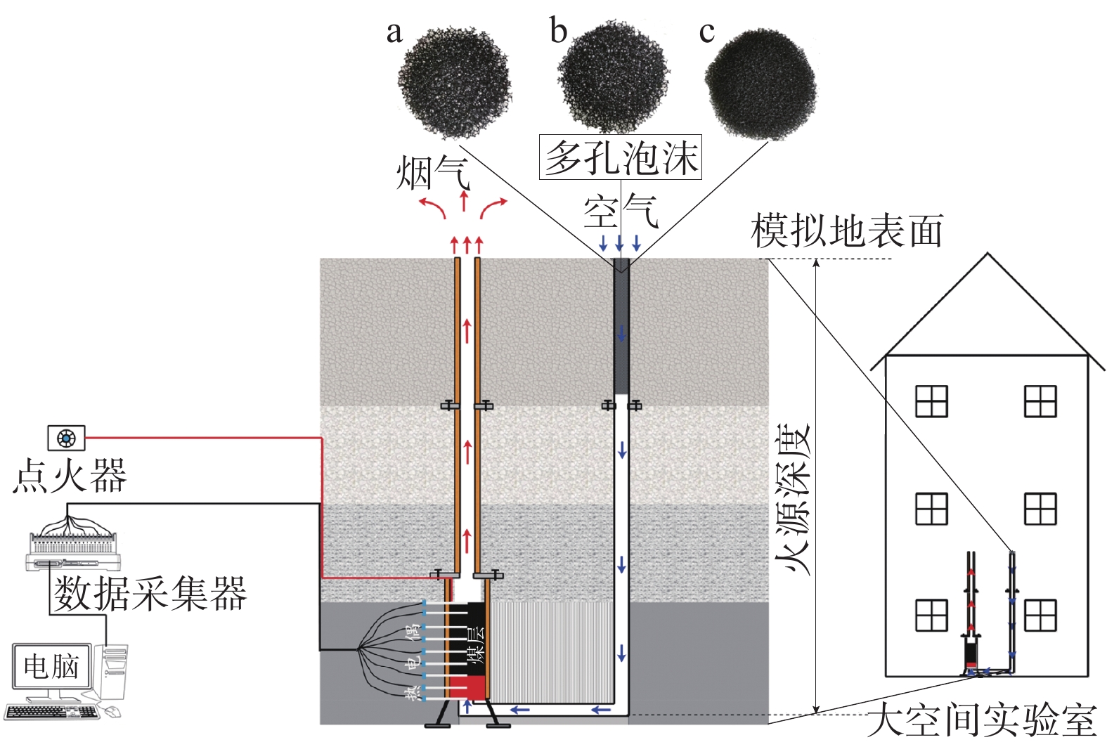
热浮力驱动地裂缝气流作用下地下煤火阴燃正向蔓延相似实验系统如图1。
![]() 图 1 热浮力驱动地裂缝气流作用下地下煤火阴燃实验示意图Figure 1. Schematic diagram of underground coal smoldering fire experiment
图 1 热浮力驱动地裂缝气流作用下地下煤火阴燃实验示意图Figure 1. Schematic diagram of underground coal smoldering fire experiment实验装置分为供氧管道、燃烧炉和排气管道,3部分组合成1个U形管道,将U形管道的顶面视为模拟的地面,顶面以下的空间区域相当于地下空间。燃烧区域简化为(直径12 cm×高度60 cm)的垂直管道,通风管道由垂直的排气管道和L形的供氧管道组成,分别安装在燃烧室的顶部和底部。2个管子的直径都为6 cm,管道的垂直长度(火源深度)为2.6 m。该实验与现场原型的相似比为1∶20,可以较好地反映地下煤火气体运移的本质特点[25]。
此外,地下煤火供氧受限重要的因素之一是地裂缝等通道空间小[26-27]。实验在供氧管道入口填入厚度为40 cm的大、中、小3种不同孔径的泡沫(分别对应孔隙率为0.9645、0.9522、0.9223的泡沫a、泡沫b、泡沫c),模拟地裂缝渗透性的影响作用。燃烧炉内填放约15 cm厚的烟煤煤层,煤颗粒平均直径为6 mm。点火器放置在煤层下方,以15~20 kW/m2的功率加热煤层,产生烟气。在烟气的热浮力驱动作用下,空气通过供氧管道进入燃烧炉参与煤阴燃反应,且供氧方向与煤阴燃蔓延方向一致,即阴燃正向蔓延。燃烧炉的中心设有7个K型热电偶(TC1~TC7),测量煤火蔓延温度和烟气温度。当TC1的温度达到500 ℃时,点火器自动关闭。地下煤火在热浮力驱动供氧条件下自维持地蔓延,直至煤层烧完。为了排除外部风对实验结果的影响,相似实验装置放置在大空间实验室内。每组实验至少重复2次。
2. 数学模型
2.1 煤阴燃化学反应体系
2.1.1 煤阴燃单步反应
煤阴燃反应十分复杂,目前其具体的反应机制尚没有完全认识清楚。目前大部分研究将煤燃烧简化为单步反应[28]:
$$\text { coal } \cdot \mathrm{H}_2 \mathrm{O}+v_{\mathrm{o}, \mathrm{O}_2} \mathrm{O}_2 \rightarrow v_{\mathrm{o}, \mathrm{a}} \text { ash }+v_{\mathrm{o}, \mathrm{g}} \text { gas }$$ (1) 式中:$v_{\mathrm{o}, \mathrm{O}_2}、v_{{\mathrm{o}},{\mathrm{a}}}、v_{{\mathrm{o}},{\mathrm{g}}} $分别为氧气、灰分反应生成的气体在氧化过程的反应系数。
2.1.2 煤阴燃三步反应
煤阴燃单步反应对于阴燃蔓延模型来说过于简单,因为忽略了水分蒸发和热解等吸热反应,但这些吸热反应对于地下煤火阴燃蔓延温度、速率和自维持性等都具有重要的影响作用。因此采用三步阴燃化学反应,如式(2)~式(4)[29](煤中的水分简化为固体成分看待,不考虑相变和环境中的水分影响):
水分蒸发:
$$ \operatorname{coal} \cdot v_{\mathrm{w}, \mathrm{dr}} \mathrm{H}_2 \mathrm{O} \rightarrow \operatorname{coal}+v_{\mathrm{w}, \mathrm{dr}} \mathrm{H}_2 \mathrm{O}(\mathrm{g}) $$ (2) 式中:$v_{\mathrm{w}, \mathrm{dr}} $为水分蒸发过程的反应系数。
煤热解:
$$ \text { coal } \rightarrow v_{\mathrm{p}, \mathrm{ch}} \text { char }+v_{\mathrm{p}, \mathrm{g}} \text { gas } $$ (3) 式中:$v_{\mathrm{p}, \mathrm{ch}}、v_{{\mathrm{p}},{\mathrm{g}}} $分别为碳、反应生成的气体在热解过程的反应系数。
碳氧化:
$$ \text { char }+v_{\mathrm{o}, \mathrm{O}_2} \mathrm{O}_2 \rightarrow v_{\mathrm{o}, \mathrm{a}} \text { ash }+v_{\mathrm{o}, \mathrm{g}} \text { gas } $$ (4) 采用阿伦尼乌斯公式计算每步反应速率[30]:
$$r_{{j}}=\rho_i Y_{{i}}^{n_1} Y_{\mathrm{O}_2}^{n_{\mathrm{O}_2}} A_{{j}} {\mathrm{e}}^{-E_{{j}} / R T} $$ (5) 式中:rj为反应速率,kg/(m3·s);ρi为不同固体组分密度,kg/m3;Yi、$Y_{{\mathrm{O}}_2} $分别为固体组分和氧气的质量分数;Aj为各分步反应的指前因子,1/s;Ej为各分步反应的活化能,kJ/mol;ni为固体组分的反应级数;R为摩尔气体常量;T为热力学温度,K;$n_{{\mathrm{O}}_2} $为氧气的反应级数。
对于阴燃三步反应体系而言,式(2)~式(5)包含A、E、n未知的动力学参数。为了求解这些参数,开展了2、5、10 K/min 3种升温速率的煤燃烧热重实验。根据质量守恒和热重实验数据,采用遗传算法计算求得最优的动力学参数,关于阴燃多步反应动力学参数等的遗传算法优化求解可参见文献[29-31]。煤阴燃反应动力学参数、化学计量系数和反应热见表1。
表 1 煤阴燃反应动力学参数、化学计量系数和反应热Table 1. Kinetic parameters, stoichiometric coefficients and reaction heat of coal smoldering reaction反应 指前因子
(lgAj)活化能
(Ej)/(kJ·mol−1)反应级数
(ni)化学计量
系数
(vj)反应热
(ΔH)/(MJ·kg−1)水分蒸发 8.120 0 67.800 0 2.3702 0.200 2.260 00 煤热解 10.4136 194.6619 9.2711 0.731 0.335 00 碳氧化 8.0743 166.2853 2.1104 0.209 28.35132 2.2 控制方程
2.2.1 热浮力驱动作用下气流渗流方程
热浮力驱动作用下气流运动基本符合达西定律。
因此,气流渗流方程可表示为:
$$ u=c \dfrac{\kappa \rho_{\mathrm{a}} g\left(1-T_{\mathrm{a}} / T_{\mathrm{g}}\right)}{\mu}$$ (6) 式中:u为气流速度,m/s;κ为渗透系数,m2;μ为空气动力黏性系数,kg/(m·s);ρa为空气密度,kg/m3;g为加速度,m/s2;Ta、Tg分别为环境温度和烟气温度,℃;c为填充泡沫后的等效通风阻力系数,大、中、小3种口径其值分别为0.40、0.35、0.23。
2.2.2 质量守恒方程
煤阴燃多步反应包含4个组分,分别为水分、煤、碳和灰分,其各自的质量守恒方程如式(7)~式(10)。
$$ \dfrac{{\mathop {{\rho _{\text{s}}}}\limits^\_ \partial {Y_{\text{w}}}}}{{\partial t}} = - {r_w} $$ (7) $$ \dfrac{{\mathop {{\rho _{\text{s}}}}\limits^\_ \partial {Y_{{\mathrm{coal}}}}}}{{\partial t}} = - {r_{\mathrm{p}}} $$ (8) $$ \dfrac{\bar{\rho}_{\mathrm{s}} \partial Y_{\mathrm{char}}}{\partial t}=v_{\mathrm{p}, \mathrm{ch}} r_{\mathrm{p}}-r_{\mathrm{o}} $$ (9) $$\dfrac{\bar{\rho}_{\mathrm{s}} \partial Y_{\mathrm{ash}}}{\partial t}=v_{\mathrm{o}, \mathrm{a}} r_{\mathrm{o}} $$ (10) 式中:$\bar{\rho}_{\mathrm{s}} $为固体平均密度,kg/m3;Yw、Ycoal、Ychar、Yash分别为水分、煤、碳、灰分的质量分数;t为时间,s;rw、rp、ro分别为水分蒸发、煤热解、碳氧化的反应速率,kg/(m3·s)。
4种组分混合的固体总体质量守恒方程为:
$$ \dfrac{\partial \bar{\rho}_{\mathrm{s}}}{\partial t}=-r_w+\left(v_{\mathrm{p}, \mathrm{ch}}-1\right) r_{\mathrm{p}}+\left(v_{\mathrm{o}, \mathrm{a}}-1\right) r_{\mathrm{o}}$$ (11) 2.2.3 能量守恒方程
假设气、固两相达到了热均衡状态,则能量守恒方程为:
$$\begin{split} &\begin{gathered} \bar{\rho} \bar{C} \dfrac{\partial T}{\partial t} =\left(\bar{\lambda}+\beta\left(T-T_{\mathrm{a}}\right)^3\right) \nabla^2 T+\left(r_{\mathrm{o}} \Delta H_{\mathrm{o}}\right.- \\ \left.r_{\mathrm{p}} \Delta H_{\mathrm{p}}-r_{\mathrm{w}} \Delta H_{\mathrm{w}}\right) \end{gathered}\\[-16pt]& \end{split}$$ (12) 式中:$ \bar{\rho } $为平均密度,kg/m3;$ \bar{C} $为平均比热容,J/(kg·K);$ \bar{\lambda } $为平均导热率,J/(kg·K);$ \beta $为辐射换热系数,W/(m·K4);$ \nabla $为微分算子;$\Delta H_{\mathrm{o}}、\Delta H_{\mathrm{p}}、 \Delta H_{\mathrm{w}} $分别为氧化过程、热解过程、蒸发过程的反应热,MJ/kg。
其中,
$$ \bar{\rho}=\varepsilon \rho_{\mathrm{g}}+(1-\varepsilon) \overline{\rho_{\mathrm{s}}} $$ (13) $$\bar{C}=\varepsilon C_{\mathrm{g}}+(1-\varepsilon) \overline{C_{\mathrm{s}}} $$ (14) $$\bar{\lambda}=\varepsilon \lambda_{\mathrm{g}}+(1-\varepsilon) \bar{\lambda}_{\mathrm{s}}+\lambda_{\mathrm{q}} $$ (15) $$\lambda_{\mathrm{q}}=\beta\left(T-T_{\mathrm{a}}\right)^3 $$ (16) 式中:ε为煤层孔隙率;$ \rho_{\mathrm{g}} $为气体的密度,kg/m3;$ {\overline{ \rho _{\mathrm{s}}} }$为固体的平均密度,kg/m3;$ {\overline{{C}}_{{\mathrm{s}}} }$为固体的平均比热容,J/(kg·K);Cg为气体的比热,J/(kg·K);$ {\bar{\lambda }}_{{\mathrm{s}}} $为固体的平均导热率, W/(m·K);λq为辐射导热系数,W/(m·K);$\lambda_{\mathrm{g}} $为气体的导热率,W/(m·K)。
$$\left\{\begin{array}{c} {\overline{\rho }}_{{\mathrm{s}}}={\displaystyle \sum {\rho }_{{i}}{Y}_{{i}}}\\ {\overline{C}}_{{\mathrm{s}}}={\displaystyle \sum {C}_{{i}}{Y}_{{i}}}\\ {\overline{\lambda }}_{{\mathrm{s}}}={\displaystyle \sum {\lambda }_{{i}}{Y}_{{i}}}\end{array} \right.$$ (17) 式中:Ci为固体组分的比热容,J/(kg·K);λi为固体组分的导热率,W/(m·K);i = H2O、coal、C、ash。
2.2.4 氧气运输方程
物质传递方程涉及的物质主要包括氧气、氮气和烟气(主要为一氧化碳和二氧化碳)。研究不考虑气相反应,且忽略烟气-空气之间的组分浓度浮力,只考虑氧气组分的运输,如式(18)。
$$ \begin{aligned} \dfrac{\partial\left(\rho_{\mathrm{a}} Y_{\mathrm{O}_2} \varepsilon\right)}{\partial t} + \nabla\left(\rho_{\mathrm{a}} Y_{\mathrm{O}_2} u \varepsilon\right) = D \varepsilon \nabla^2\left(\rho_{\mathrm{a}} Y_{\mathrm{O}_2}\right) -v_{\mathrm{o}, \mathrm{O}_2} r_{\mathrm{o}} \end{aligned}$$ (18) 式中:$ D $为空气扩散系数,m2/s。
3. 数值计算
3.1 边界和初始条件
计算域的温度场边界条件为:
$$ \begin{split} \left\{\begin{array}{l}\begin{array}{l}左右两侧:-\lambda \dfrac{\partial T}{\partial x}|{}_{x=\pm {a}}=-{H}_{b}\left(T-{T}_{{\mathrm{a}}}\right)\\ \quad\, 下边界:-\lambda \dfrac{\partial T}{\partial y}|{}_{y=0}=q\end{array}\\ \quad \;\; \;上边界:-\lambda \dfrac{\partial T}{\partial y}|{}_{y=l}=-{H}_{{\mathrm{c}}}\left(T-{T}_{{\mathrm{a}}}\right)\end{array} \right. \end{split}$$ (19) 式中:Hb、Hc分别为反应区域侧边、上边界的对流换热系数,W/(m2·K);q为热通量,kW/m2;λ为导热率,W/(m·K)。
$$q=\left\{\begin{array}{l} q_1=10 \mathrm{~kW} / \mathrm{m}^2\;\;\; 0 \leqslant t \leqslant 4\;000 \mathrm{~s} \\ q_2=0\;\;\;\;\;\,\qquad \qquad \quad t>4\;000 \mathrm{~s} \end{array}\right.$$ (20) 氧气运输的边界条件为:
$$\left\{\begin{array}{l} \text {左右两侧: }-\left.D \varepsilon \frac{\partial\left(\rho_g Y_{\mathrm{O}_2}\right)}{\partial y}\right|_{y= \pm a}=0 \\ \quad\, \text {下边界: }\left.Y_{\mathrm{O}_2, 0}\right|_{y=0}=0.21 \\ \quad\; \text {上边界: }-\left.D \varepsilon \frac{\partial\left(\rho_g Y_{\mathrm{O}_2}\right)}{\partial y}\right|_{y=l}=h_{\mathrm{m}}\left(Y_{\mathrm{O}_2, 0}-Y_{\mathrm{O}_2}\right) \end{array}\right. $$ (21) 式中:$Y_{\mathrm{O}_2} $为初始时刻氧气的体积分数;$ {h}_{{\mathrm{m}}} $为模型中的反应深度比,当$ y=l $时,$ {h}_{{\mathrm{m}}} $为1。
数值计算的初始条件为:
$$ \begin{aligned} T_0=T_{\mathrm{a}}, \; \rho_{{\mathrm{s}}, 0}=\rho_{\text {coal }, 0}, \;Y_{{\mathrm{w}}, 0}=0.2, \\ Y_{\text {coal}, 0}=0.8 \;\rho_{{\mathrm{g}}, 0}=\rho_a,\;Y_{\mathrm{O}_2, 0}=0.21\end{aligned} $$ 式中:T0为初始时刻温度,K;ρs,0为初始时刻固体密度,kg/m3;ρcoal,0为初始时刻煤的密度,kg/m3;ρg,0为初始时刻气体密度,kg/m3;Yw,0、Ycoal,0分别为初始时刻水分、煤的质量分数。
3.2 输入参数和网格划分
数值计算模型中输入的参数值为:①比热容:水比热容Cw=4 168 J·/(kg·K),煤比热容Cc=1 320 J·/(kg·K),碳Cch=1 260 J·/(kg·K),灰分比热容Cash=880 J·/(kg·K),气体比热容Cg=1 000 J·/(kg·K);②空气扩散系数D=1.5×10−5 m2/s;③对流换热系数Ha=6.8 W/(m2·K);④对流换热系数Hb=0.12 W/(m2·K);⑤导热系数:水导热系数λw=0.6 W/(m·K),煤导热系数λc=0.2 W/(m·K),碳导热系数λch=0.26 W/(m·K),灰分导热系数λash=0.8 W/(m·K),气体导热系数λg=0.025 8 W/(m·K);⑥气体常数R=8.314 J/(mol·K);⑦环境温度Ta=293.15 K;⑧氧气初始质量分数Yo=0.21;⑨辐射换热系数β=3×10⁻⁹ W(m·K4);⑩孔隙率ε=0.55;⑪渗透系数κ=4.436 7×10⁻⁷ m2;⑫空气密度ρa=1.293 kg/m3;⑬煤密度ρc=1 595 kg/m3;⑭空气动力黏性系数µ=1.85×10−5 kg/(m·s)。
采用自由三角形网格进行划分。利用现有参数对模型进行试算,其表明:采用细化网格(网格单元数为2 572)能使数值计算结果精度(最小单元质量0.32,平均单元质量0.92)和收敛性较好,且计算效率高。
4. 模拟结果
4.1 模型验证
将厚度为40 cm的大、中、小3种不同孔径泡沫,填入供氧管道内,实验观察和模拟分析其蔓延情况。热浮力驱动作用下地下煤火阴燃正向蔓延模型验证如图2。不同泡沫孔隙率条件下供氧速率如图3。
![]() 图 2 热浮力驱动作用下地下煤火阴燃正向蔓延模型验证Figure 2. Validation of the proposed model against with experimental data
图 2 热浮力驱动作用下地下煤火阴燃正向蔓延模型验证Figure 2. Validation of the proposed model against with experimental data![]() 图 3 不同泡沫孔隙率条件下供氧速率Figure 3. Oxygen supply rate under different foam porosity conditions
图 3 不同泡沫孔隙率条件下供氧速率Figure 3. Oxygen supply rate under different foam porosity conditions在实验条件下,地下煤火阴燃蔓延的峰值温度区间为(662±27~850±68) ℃,蔓延速率为(0.20±0.13~0.49±0.27)cm/h;与野外现场观测的结果比较接近[7,32-33];与空心供氧管道(不填充多孔泡沫)条件相比,其峰值温度低、蔓延速率小[17],但与地表泥炭向地下深处正向蔓延相比,两者的峰值温度和蔓延速率基本相同[34]。
由图2可知:随着渗透性的减小,蔓延的峰值温度降低、蔓延速率变慢,这主要因为渗透性低、供氧难。
由图2可知:三步反应模型数值计算结果与实验测量结果非常接近;单步反应模型数值计算结果在阴燃正向蔓延的峰值温度上较为接近,但蔓延速率差别较大,单步反应模型不能很好地反映实际的煤火阴燃蔓延情况。综上所述,三步反应模型明显优于单步反应模型。同时说明提出的新的三步反应模型能有效地预测热浮力驱动地裂缝气流作用自下地下煤火阴燃正向蔓延。
4.2 热浮力驱动下地下煤火阴燃正向蔓延机制
煤在点火器加热作用下生产烟气,烟气温度高于空气产生热浮力,在“U”形管道进入口两端形成压差,使得空气向下运输进入供氧管道和燃烧炉,促使煤阴燃和蔓延。随着加热的持续,烟气温度增加,热浮力增加,从而供氧速率增大;使得氧化反应增强、放热增大,继而进一步促进供氧。供氧速率在点火和火蔓延初期随着时间的推移迅速增大。当关闭点火器之后,只要烟气温度达到一定的值,且整个煤层空间的放热速率大于等于散热速率,则可以在热浮力驱动地裂缝气流供氧条件下地下煤火维持阴燃正向蔓延。
t=6、18、30 h 3个时间在热浮力驱动作用下地下煤火蔓延特征如图4。
![]() 图 4 泡沫孔隙率为0.9522条件下t=6 h(第1列)、18 h(第2列)和30 h(第3列)的温度场及氧气体积分数、煤、碳、灰分质量分数分布Figure 4. Cloud diagrams of temperature field, oxygen, coal, carbon and ash mass fraction distribution (from top to bottom) of t=6 h (the first column), 18 h (the second column) and 30 h (the third column) with condition of foam porosity of 0.952 2
图 4 泡沫孔隙率为0.9522条件下t=6 h(第1列)、18 h(第2列)和30 h(第3列)的温度场及氧气体积分数、煤、碳、灰分质量分数分布Figure 4. Cloud diagrams of temperature field, oxygen, coal, carbon and ash mass fraction distribution (from top to bottom) of t=6 h (the first column), 18 h (the second column) and 30 h (the third column) with condition of foam porosity of 0.952 2由图4可知:阴燃正向蔓延的高温峰值(Tp=750 ℃)的位置与氧气体积分数骤降梯度的位置是一致的,因为碳氧化是阴燃蔓延放热的主要热源,这也是地下煤火阴燃正向蔓延受供氧控制的主要原因。这些位置还与碳的质量分数骤降梯度以及灰分质量分数的骤增梯度的位置也是相同的,其原因在于在构建的三步阴燃反应体系中碳的消耗和灰分的生成主要是在于碳的氧化反应。然而,煤的质量分数分布特点则与氧气、碳和灰分不同,因为煤主要因为热解反应而消耗,而热解反应不需要氧气参与,因此碳的质量分数空间分布与氧气的分布基本没有直接的关联。值得注意的是,在阴燃正向蔓延的初期,煤和碳质量分数空间分布可能存在骤增和骤降2个梯度,因为热量在煤层内部传导较慢,阴燃前锋(碳氧化反应位置)远端的煤温度低,尚未开始热解反应,没有生成碳。
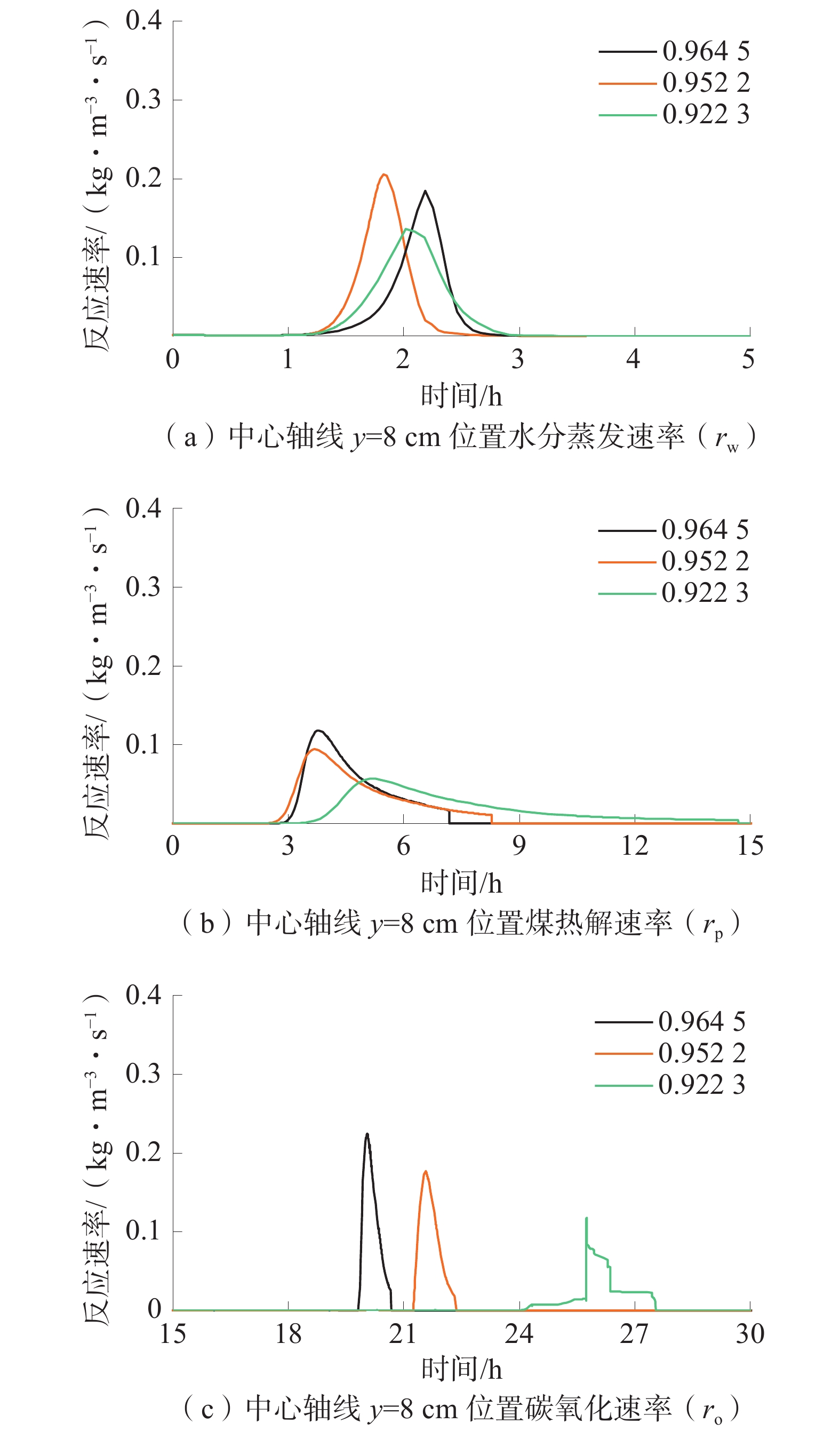
中孔隙率泡沫条件的中心轴线y=2、8、12 cm 3个位置的水分蒸发(rw)、煤热解(rp)和碳氧化(ro)反应速率随时间的变化情况如图5。大、中和小3种孔隙率泡沫条件下同一位置(y=8 cm)的水分蒸发(rw)、煤热解(rp)和碳氧化(ro)反应速率随时间变化如图6。
![]() 图 5 泡沫孔隙率为0.9522条件下中心轴线3个不同位置的反应速率Figure 5. Chemical reaction rates of three different positions at the central axis with condition of foam porosity of 0.952 2
图 5 泡沫孔隙率为0.9522条件下中心轴线3个不同位置的反应速率Figure 5. Chemical reaction rates of three different positions at the central axis with condition of foam porosity of 0.952 2由图5可知:水分蒸发反应在煤层中蔓延的速率最快,从y=2 cm至12 cm,仅需不到5 h的时间;相同的距离,煤热解则需要约15 h,这比水分蒸发慢了10 h,其可能原因主要是煤质量分数远大于水分、导热较慢且热解温度高于水的沸点等;氧化反应的蔓延速率最慢,10 cm的距离需约20 h的时间,这主要原因在于热浮力驱动作用下的供氧速率小(umax∈(5 mm/s, 8 mm/s))。说明了地下煤火阴燃正向蔓延主要受供氧控制,在某种程度上也证明了本文构建的阴燃三步反应体系及控制方程等蔓延模型能够较好地实现阴燃蔓延的供氧控制,有效地预测地下煤火阴燃蔓延。
由图6可知:随着孔隙率的减小,渗透性降低,供氧速率减小,从而较大地降低了地下煤火阴燃正向蔓延峰值和速率;与水分蒸发和煤热解反应相比,渗透性对氧化反应速率的影响最大;随着孔径减小,ro的最大值由0.25 kg/(m3·s)降至0.15 kg/(m3·s),其出现时间由20 h延迟至27 h。
除此之外,渗透性对水分蒸发和煤热解反应也有一定的影响作用。渗透性降低,水分蒸发和热解反应速率都会减小,而其持续时间则稍有延长。由反应速率的阿伦尼乌斯公式可知,主要原因在于氧化反应得到抑制,放热减小、温度降低,使得水分蒸发和热解反应速率减小。进一步揭示了地下煤火阴燃供氧控制的机制的具体内涵为:供氧不仅会直接影响氧化反应,而且会间接影响水分蒸发和热解反应。
![]() 图 6 不同泡沫孔隙率条件下中心轴线y=8 cm位置水分蒸发(rw)、煤热解(rp)和=碳氧化(ro)反应速率Figure 6. Reaction rates of water evaporation(rw), coal pyrolysis(rp) and carbon oxidation(ro) at y=8 cm with different porosity of foam
图 6 不同泡沫孔隙率条件下中心轴线y=8 cm位置水分蒸发(rw)、煤热解(rp)和=碳氧化(ro)反应速率Figure 6. Reaction rates of water evaporation(rw), coal pyrolysis(rp) and carbon oxidation(ro) at y=8 cm with different porosity of foam5. 结 语
构建了热浮力驱动地裂缝气流作用下地下煤火阴燃正向蔓延模型,通过与实验结果对比,证明了构建模型的有效性;揭示了热浮力驱动地裂缝气流作用下地下煤火阴燃正向蔓延机制:供氧不仅会直接影响氧化反应,而且会间接影响水分蒸发和热解反应;构建的模型能预测地下煤火阴燃正向蔓延高温区域的温度、迁移速率、阴燃多步反应速率以及氧气、煤、碳和灰分质量分数的时空演化。
-
![]()
图 1 热浮力驱动地裂缝气流作用下地下煤火阴燃实验示意图
Figure 1. Schematic diagram of underground coal smoldering fire experiment
![]()
图 2 热浮力驱动作用下地下煤火阴燃正向蔓延模型验证
Figure 2. Validation of the proposed model against with experimental data
![]()
图 3 不同泡沫孔隙率条件下供氧速率
Figure 3. Oxygen supply rate under different foam porosity conditions
![]()
图 4 泡沫孔隙率为0.9522条件下t=6 h(第1列)、18 h(第2列)和30 h(第3列)的温度场及氧气体积分数、煤、碳、灰分质量分数分布
Figure 4. Cloud diagrams of temperature field, oxygen, coal, carbon and ash mass fraction distribution (from top to bottom) of t=6 h (the first column), 18 h (the second column) and 30 h (the third column) with condition of foam porosity of 0.952 2
![]()
图 5 泡沫孔隙率为0.9522条件下中心轴线3个不同位置的反应速率
Figure 5. Chemical reaction rates of three different positions at the central axis with condition of foam porosity of 0.952 2
![]()
图 6 不同泡沫孔隙率条件下中心轴线y=8 cm位置水分蒸发(rw)、煤热解(rp)和=碳氧化(ro)反应速率
Figure 6. Reaction rates of water evaporation(rw), coal pyrolysis(rp) and carbon oxidation(ro) at y=8 cm with different porosity of foam
表 1 煤阴燃反应动力学参数、化学计量系数和反应热
Table 1 Kinetic parameters, stoichiometric coefficients and reaction heat of coal smoldering reaction
反应 指前因子
(lgAj)活化能
(Ej)/(kJ·mol−1)反应级数
(ni)化学计量
系数
(vj)反应热
(ΔH)/(MJ·kg−1)水分蒸发 8.120 0 67.800 0 2.3702 0.200 2.260 00 煤热解 10.4136 194.6619 9.2711 0.731 0.335 00 碳氧化 8.0743 166.2853 2.1104 0.209 28.35132  下载: 导出CSV
-
[1] STRACHER G B. Coal fires burning around the world: a gobal catastrophe[J]. International Journal of Coal Geology, 2004, 59(1/2): 1−6.
[2] 张建民,管海晏,曹代勇,等. 中国地下煤火研究与治理 [M]. 北京:煤炭工业出版社,2008. [3] SONG Z, KUENZER C. Coal fires in China over the last decade: A comprehensive review[J]. International Journal of Coal Geology, 2014, 133: 72−99.
[4] 邓军,李贝,王凯,等. 我国煤火灾害防治技术研究现状及展望[J]. 煤炭科学技术,2016,44(10):1−7. DENG Jun, LI Bei, WANG Kai, et al. Research status and outlook on prevention and control technology of coal fire disaster in China[J]. Coal Scienceand Technology, 2016, 44(10): 1−7.
[5] 梁运涛,侯贤军,罗海珠,等. 我国煤矿火灾防治现状及发展对策[J]. 煤炭科学技术,2016,44(6):1−6. LIANG Yuntao, HOU Xianjun, LUO Haizhu, et al. Development countermeasures and current situation of coal mine fire prevention & extinguishing in China[J]. Coal Science and Technology, 2016, 44(6): 1−6.
[6] 秦波涛,仲晓星,王德明,等. 煤自燃过程特性及防治技术研究进展[J]. 煤炭科学技术,2021,49(1):66−99. QIN Botao, ZHONG Xiaoxing, WANG Deming, et al. Research progress of coal spontaneous combustion process characteristics and prevention technology[J]. Coal Science and Technology, 2021, 49(1): 66−99.
[7] SHI B, SU H, LI J, et al. Clean power generation from the intractable natural coalfield fires: turn harm into benefit[J]. Scientific Reports, 2017, 7(1): 5302. doi: 10.1038/s41598-017-05622-4
[8] OHLEMILLER T J, LUCCA D A. An experimental comparison of forward and reverse smolder propagation in permeable fuel beds[J]. Combust Flame, 1983, 54(1): 131−147.
[9] REIN G. Smouldering combustion phenomena in science and technology[J]. International Review of Chemical Engineering, 2009(1): 3−18.
[10] 刘晓晨,武建军,刘明,等. 气象条件对地下煤火浅层温度的影响[J]. 煤炭学报,2011,36(8):1334−1341. LIU Xiaochen, WU Jianjun, LIU Ming, et al. Effect of local meteorological conditions on shallow subsurfacetemperature above underground coal fire[J]. Journal of China Coal Society, 2011, 36(8): 1334−1341.
[11] SONG Z, ZHU H, XU J, et al. Effects of atmospheric pressure fluctuations on hill-side coal fires and surface anomalies[J]. International Journal of Mining Science and Technology, 2015, 25(6): 1037−1044. doi: 10.1016/j.ijmst.2015.09.024
[12] SONG Z, ZHU H, TAN B, et al. Numerical study on effects of air leakages from abandoned galleries on hill-side coal fires[J]. Fire Safety Journal, 2014, 69: 99−110. doi: 10.1016/j.firesaf.2014.08.011
[13] 曾强,常心坦. 新疆煤田火区火风压模式研究及其应用[J]. 煤炭学报,2007,32(9):955−958. ZENG Qiang, CHANG Xintan. Study on the model of fire-heating airflow and its application to Xinjiang coal-field fires[J]. Journal of China Coal Society, 2007, 32(9): 955−958.
[14] 邓军,文虎,张辛亥,等. 煤田火灾防治理论与技术 [M]. 徐州:中国矿业大学出版社,2014. [15] IDE S T, ORR JR F M. Comparison of methods to estimate the rate of CO2 emissions and coal consumption from a coal fire near Durango, CO[J]. International Journal of Coal Geology, 2011, 86(1): 95−107. doi: 10.1016/j.coal.2010.12.005
[16] KREVOR S C M, IDE T, BENSON S M, et al. Real-time tracking of CO2 injected into a subsurface coal fire through high-frequency measurements of the 13CO2 signature[J]. Environmental Science & Technology, 2011, 45(9): 4176−4186.
[17] SONG Z, HUANG X, KUENZER C, et al. Chimney effect induced by smoldering fire in a U-shaped porous channel: A governing mechanism of the persistent underground coal fires[J]. Process Safety and Environmental Protection, 2020, 136: 136−147. doi: 10.1016/j.psep.2020.01.029
[18] HUANG J, BRUINING J, WOLF K-H. Modeling of gas flow and temperature fields in underground coal fires[J]. Fire Safety Journal, 2001, 36(5): 477−489. doi: 10.1016/S0379-7112(01)00003-0
[19] WOLF K-H, BRUINING H. Modelling the interaction between underground coal fires and their roof rocks[J]. Fuel, 2007, 86(17/18): 2761−2777.
[20] WESSLING S, KESSELS W, SCHMIDT M, et al. Investigating dynamic underground coal fires by means of numerical simulation[J]. Geophysical Journal International, 2008, 172(1): 439−454. doi: 10.1111/j.1365-246X.2007.03568.x
[21] 宋泽阳,朱红青,徐纪元,等. 地下煤火高温阶段贫氧不完全燃烧耗氧速率的计算[J]. 煤炭学报,2014,39(12):2439−2445. SONG Zeyang, ZHU Hongqing, XU Jiyuan, et al. An approach to calculate oxygen consumption rate of underground coal fires with lean oxygen concentration and incomplete combustion at high temperature[J]. Journal of China Coal Society, 2014, 39(12): 2439−2445.
[22] WANG Y, LI X, GUO Z. Prediction of self-ignition fire propagatioin and coal loss in an inclined seam[J]. Heat Transfer Research, 2018, 49(9): 827−845. doi: 10.1615/HeatTransRes.2018020029
[23] TANG Y, ZHONG X, LI G, et al. Simulation of dynamic temperature evolution in an underground coal fire area based on an optimised thermal–hydraulic–chemical model[J]. Combustion Theory and Modelling, 2019, 23(1): 127−146. doi: 10.1080/13647830.2018.1492742
[24] BUSTAMANTE RúA M O, DAZA ARAGóN A J, BUSTAMANTE BAENA P. A study of fire propagation in coal seam with numerical simulation of heat transfer and chemical reaction rate in mining field[J]. International Journal of Mining Science and Technology, 2019, 29(6): 873−879. doi: 10.1016/j.ijmst.2019.09.003
[25] 曾强. 新疆煤田火灾烟气流动与传热特性的研究[J]. 煤炭学报,2009,34(6):792−796. ZENG Qiang. Study on the regularity of gas/smoke flow and the characteristics of heat-transfer with spontaneous combustion in Xinjiang coalfield[J]. Journal of China Coal Society, 2009, 34(6): 792−796
[26] 曹代勇,樊新杰,吴查查,等. 内蒙古乌达煤田火区相关裂隙研究[J]. 煤炭学报,2009,34(8):1009−1014. CAO Daiyong, FAN Xinjie, WU Chacha, et al. Study on the fractures related with coalfield fire area in Wuda coalfield, Inner Mongolia[J]. Journal of China Coal Society, 2009, 34(8): 1009−1014.
[27] KUENZER C, STRACHER G B. Geomorphology of coal seam fires[J]. Geomorphology, 2012, 138(1): 209−222. doi: 10.1016/j.geomorph.2011.09.004
[28] ROY N C, Nakamura Y. Investigation of unsteady behaviors of forward and opposed flow combustion of solid fuel[J]. Combustion & Flame, 2016, 163: 517-531.
[29] SONG Z, FAN H, JIANG J, et al. Insight into effects of pore diffusion on smoldering kinetics of coal using a 4-step chemical reaction model[J]. Journal of Loss Prevention in the Process Industries, 2017, 48: 312−319. doi: 10.1016/j.jlp.2017.04.020
[30] HUANG X, REIN G. Smouldering combustion of peat in wildfires: inverse modelling of the drying and the thermal and oxidative decomposition kinetics[J]. Combust Flame, 2014, 161(6): 1633−1644. doi: 10.1016/j.combustflame.2013.12.013
[31] REIN G, LAUTENBERGER C, FERNANDEZ-PELLO A C, et al. Application of genetic algorithms and thermogravimetry to determine the kinetics of polyurethane foam in smoldering combustion[J]. Combust Flame, 2006, 146(1): 95−108.
[32] SCHLöMER S, TESCHNER M, POGGENBURG J, et al. Gas and temperature monitoring of a spontaneous coal seam fire in Wuda Coal Mining Area [C]//Beijing: Tsinghua University Press and Springer Verlag, 2008: 277-305.
[33] SCHAUMANN G. Geophysical investigation of Wuda coal mining area, Inner Mongolia: electromagnetics and magnetics for coal fire detection [C]//Beijing: Tsinghua University Press and Springer Verlag, 2008: 336-349.
[34] HUANG X, REIN G. Downward spread of smouldering peat fire: the role of moisture, density and oxygen supply[J]. International Journal of Wildland Fire, 2017, 26(11): 907−918. doi: 10.1071/WF16198
计量
- 文章访问数: 54
- HTML全文浏览量: 14
- PDF下载量: 10
